How to Choose the Right Vertical Connector in 2026?

Time:2026-10-03 Author:Isabella
0%

Choosing the right Vertical Connector in 2026 requires more than matching a catalog number. Board space is shrinking. Data rates are rising. Thermal margins are narrowing. A connector that fits mechanically may still fail electrically.

Grand View Research estimates the global connector market was worth roughly USD 84 billion in 2023, with continued growth through 2030. Bishop & Associates’ Connector Industry Forecast also highlights sustained demand from automotive electronics, telecommunications, computing, and industrial systems. These figures show momentum, but they do not make selection simple. Market growth can hide practical failures, including weak retention, poor shielding, excessive insertion force, or unstable performance after repeated mating.

Signal integrity deserves special attention. Dr. Eric Bogatin, a recognized signal-integrity educator and connector engineering authority, states, “The signal is not the voltage; the signal is the change in voltage.” His point is highly relevant to Vertical Connector design. A 0.8-millimeter pitch, 10Gb/s transmission path may look efficient on paper. Yet an unsuitable contact layout can create crosstalk, impedance discontinuities, and unexpected heating.

This guide examines the decisions behind reliable selection. It considers current rating, mating cycles, pin density, insulation materials, vibration resistance, and manufacturing tolerances. It also compares vertical, right-angle, board-to-board, and wire-to-board configurations.

There is no perfect connector.

The honest challenge is balancing electrical performance, mechanical strength, cost, availability, and future upgrades. Datasheets help, but laboratory validation remains essential. A connector that works in a clean prototype may behave differently inside a hot, vibrating enclosure. That uncomfortable gap deserves careful attention in 2026.
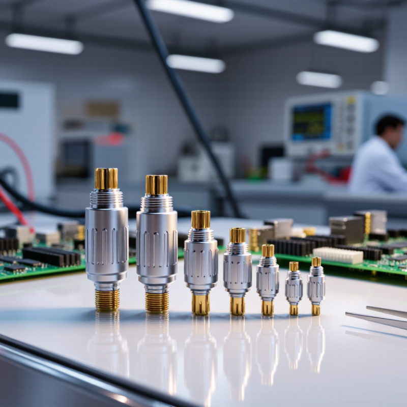
How to Choose the Right Vertical Connector in 2026?

Understanding Vertical Connector Types and Their Core Functions

Choosing a vertical connector starts with its core function, not its appearance.

A vertical wire-to-board header carries power or signals between a cable and a PCB. A board-to-board connector joins stacked circuit boards with controlled spacing. High-speed vertical backplane connectors protect signal integrity across dense equipment. Vertical coaxial or shielded types serve sensitive RF paths. Each structure solves a different mechanical and electrical problem.

The selection should match current, pitch, mating cycles, and available height. A compact 0.8 mm pitch saves board space, but it demands tighter assembly control. For high-speed links, impedance consistency and crosstalk matter more than contact count. A connector with 50 contacts may perform worse than one with 20 contacts. It depends on routing and shielding. Bishop & Associates’ 2024 connector industry analysis valued global connector sales at approximately 84.9 billion US dollars in 2023. That scale reflects rising demand for dense, reliable interconnects across computing, vehicles, and industrial controls.

Field experience adds an uncomfortable detail: a connector can pass electrical tests and still fail during vibration.

Check latch strength, plating durability, thermal expansion, and service access before approving the design. IPC test guidance and IEC 60512 methods help verify these conditions.

Measure twice. I would also question catalogue ratings. They often assume ideal temperatures, clean mating, and short traces. Real assemblies are less polite.

A 2026 design review should test the actual stack height, cable bend, insertion force, and airflow path, not only the datasheet values.

Defining Electrical, Mechanical, and Environmental Requirements

Choosing a vertical connector in 2026 starts with requirements, not catalog photos. Define voltage, current, signal speed, contact pitch, and installation direction. A 2024 Bishop & Associates market report valued global connector sales near 84 billion US dollars in 2023. That scale reflects intense application diversity, not universal compatibility.

Electrical limits must include continuous current, inrush current, dielectric strength, and acceptable voltage drop. Mechanical review should cover mating cycles, retention force, vibration, and available board height. A connector that fits once may fail after repeated servicing. IEC 60512 test methods help engineers verify these conditions under controlled procedures. Environmental selection needs equal discipline. Check temperature range, humidity, dust, salt mist, chemical exposure, and ingress protection. The 2024 MarketsandMarkets connector study forecasts continued growth through 2028, driven partly by transportation and industrial electronics. These systems often face heat, shock, and contamination together. Real testing still matters. Datasheets cannot reproduce every installation mistake.

Tips: Build a requirement table before choosing a part. Use worst-case current, not average current. Confirm creepage and clearance at the working voltage. For outdoor equipment, validate the complete assembly’s IP performance, including cable exits and seals. I have seen teams over-specify metal shells while overlooking weak latches. That choice looked robust. It was not. Leave tolerance for thermal expansion, manufacturing variation, and imperfect field alignment. Review the connector after vibration and thermal-cycle testing, then revise the specification if evidence disagrees.

How to Choose the Right Vertical Connector in 2026?

Defining electrical, mechanical, and environmental requirements

Start by matching the connector to the required electrical load, mating durability, and installation environment. The chart compares standardized IP protection levels under IEC 60529: the first digit indicates protection against solid objects and dust, while the second digit indicates protection against water. Select the lowest rating that fully meets the application requirement, then verify voltage, current, temperature range, vibration, and mating-cycle specifications separately.

Comparing Materials, Pin Layouts, and Connection Mechanisms

How to Choose the Right Vertical Connector in 2026?

Material choice affects heat, wear, and signal stability. LCP suits compact, high-temperature assemblies, while PBT often offers lower cost and strong insulation. Copper-alloy contacts need suitable plating for repeated mating. Gold improves corrosion resistance, but tin can work in controlled environments. MarketsandMarkets’ 2024 Electronic Connectors report estimates the connector market could reach over USD 100 billion by 2029. That growth reflects denser boards and higher reliability demands. Still, market growth does not guarantee a good fit.

Pin layout deserves careful review. A vertical connector with 0.5 mm pitch saves board space, but it increases inspection difficulty. Group high-speed pins with controlled ground returns. Separate power pins from sensitive signal paths. IPC-2221 guidance supports practical spacing and current-carrying analysis, but real designs can expose unexpected heating. Press-fit contacts simplify rework and avoid solder, while soldered connections usually provide stronger mechanical retention. Board-to-board compression systems can speed assembly, yet tolerance stacking may create uneven contact pressure. The first layout is often wrong.

Tips: Prototype the tallest and shortest stack-up. Measure insertion force after thermal cycling. Check pin numbering from the mating face, not the drawing view. A small mistake there can reverse an entire harness. Use the 2024 IPC International Technology Roadmap for further reliability benchmarks, especially when signal density, thermal rise, and service access compete. Perfect optimization is rare. Document the compromise.

How to Choose the Right Vertical Connector in 2026? — Comparing Materials, Pin Layouts, and Connection Mechanisms
Connector Type Typical Contact Material Common Pin Layout Typical Pitch Connection Mechanism Typical Current per Contact Typical Mating Cycles Best-Fit Applications Main Selection Considerations
Board-to-Board Mezzanine Copper alloy contacts with nickel underplating and a gold contact finish Single-row or dual-row; parallel, staggered, or matrix layouts 0.40–1.27 mm Friction fit, guided mating, or floating alignment design Approximately 0.3–3.0 A Typically 30–100 cycles Compact control boards, embedded computing, instrumentation, and portable electronics Board spacing, coplanarity, alignment tolerance, signal speed, and available PCB area
Pin Header and Socket Brass or phosphor bronze contacts; tin or gold contact finishes are commonly used Single-row, dual-row, or multi-row with straight or right-angle pins 1.27–2.54 mm Pin-and-socket friction engagement Approximately 1–3 A Typically 10–50 cycles General-purpose board interconnection, programming headers, prototypes, and internal wiring Low cost, easy sourcing, mechanical clearance, retention strength, and required serviceability
Board-to-Wire Vertical Connector Copper alloy terminals with tin or gold plating; insulating housings commonly use glass-filled thermoplastics Single-row or dual-row; polarized and keyed layouts are widely available 1.00–5.08 mm Crimp, insulation-displacement, or spring-contact termination Approximately 1–10 A Typically 10–50 cycles Power distribution, sensors, industrial controls, lighting, and equipment wiring Wire gauge, pull-out force, vibration resistance, polarization, locking, and assembly method
Wire-to-Board Spring Terminal Spring-grade copper alloy or stainless-steel spring elements with a conductive contact surface Single-row or multi-row; often arranged in compact vertical blocks 2.00–5.08 mm Push-in spring, cage-clamp, or lever-assisted clamping Approximately 2–15 A Typically 10–30 cycles Industrial sensors, control cabinets, field wiring, and applications requiring tool-free termination Wire type, conductor size, vibration level, insertion force, and ease of field maintenance
High-Speed Differential Connector Low-loss copper alloy contacts with controlled plating and high-temperature insulating materials Shielded differential pairs, ground pins, and alternating signal-ground arrangements 0.50–1.27 mm Guided blind-mate or controlled-impedance friction engagement Approximately 0.3–1.5 A Typically 30–100 cycles High-speed data links, storage systems, communication equipment, and digital backplanes Insertion loss, crosstalk, impedance control, return loss, shielding, and pair skew
Power Board-to-Board Connector High-conductivity copper alloy contacts, often with tin or silver-based finishes Large dedicated power pins with separate signal or ground contacts 2.00–8.00 mm Wipe-contact, blade-contact, or guided blind-mate mechanism Approximately 5–40 A Typically 10–50 cycles Battery systems, power supplies, motor drives, industrial controllers, and modular equipment Temperature rise, current derating, contact resistance, creepage, clearance, and mechanical retention
Coaxial or Shielded Vertical Connector Brass or copper alloy signal contacts with conductive shielding shells and plated mating surfaces Single coaxial contact or grouped shielded channels Usually 2.00 mm or larger body spacing Snap-on, threaded, push-pull, or guided blind-mate coupling Generally below 3 A Typically 100–500 cycles, depending on coupling style RF modules, wireless equipment, test fixtures, imaging systems, and shield-sensitive assemblies Frequency range, characteristic impedance, shielding effectiveness, insertion loss, and cable routing
High-Temperature Vertical Connector Heat-resistant copper alloy contacts with high-temperature plating and specialized thermoplastic or thermoset insulation Single-row, dual-row, or mixed power-and-signal layouts 1.27–5.08 mm Friction fit, latch-assisted, or screw-secured connection Approximately 1–15 A, subject to temperature derating Typically 10–50 cycles Automotive electronics, industrial drives, power conversion, and equipment near heat sources Operating temperature, thermal cycling, flammability rating, derating curve, and material compatibility
Fine-Pitch Flexible or Board-Edge Connector Phosphor bronze or copper alloy contacts with nickel underplating and a low-profile conductive finish High-density single-row contacts, staggered contacts, or edge-contact arrays 0.30–1.00 mm Sliding, zero-insertion-force, or low-insertion-force engagement Approximately 0.2–1.0 A Typically 10–30 cycles Displays, cameras, compact computing devices, medical instruments, and space-constrained modules Contact contamination, flex-cable thickness, insertion force, bend radius, and assembly precision
Technical note: The values shown are representative engineering ranges rather than universal limits. Actual ratings depend on contact spacing, conductor size, plating system, housing material, temperature, airflow, voltage, PCB layout, mating tolerance, and applicable safety standards. Always confirm the manufacturer-independent design requirements through qualification testing and the connector’s current derating curve.

Evaluating Compatibility, Performance, Safety, and Reliability

How to Choose the Right Vertical Connector in 2026?

Evaluating Compatibility, Performance, Safety, and Reliability

Choosing a vertical connector starts with physical compatibility, not appearance. Check pitch, pin count, mating height, keying, and board orientation. A connector can fit the housing yet miss the circuit board by a few millimeters. Measure the available space around cables, heat sinks, and nearby components. Fit is not enough.

Performance depends on electrical and mechanical demands. Confirm rated voltage, current, contact resistance, and signal frequency under real operating conditions. Apply derating when heat builds inside a compact enclosure. For high-speed signals, inspect impedance control, crosstalk, and grounding paths. Test it cold. Then test it after repeated heating cycles. A clean laboratory result may not represent field use.

Safety and reliability require evidence, not assumptions. Review insulation distance, flame resistance, locking strength, and protection against reverse insertion. Consider vibration, humidity, dust, corrosion, and the expected mating cycles. Traceable test records improve confidence during design reviews and maintenance. A common mistake is trusting a datasheet without checking assembly variation. Small gaps matter. Engineers should also question whether every requirement is truly necessary, because unnecessary complexity can create new failure points. In my view, a short prototype run with visual inspection, pull testing, and temperature monitoring often reveals weaknesses earlier than a polished final sample.

Selecting the Best Vertical Connector for Your 2026 Application

Selecting the best vertical connector for your 2026 application starts with the real assembly, not the catalog drawing. Measure board spacing, mating direction, current load, voltage, vibration, and available stack height. A connector may fit perfectly in CAD but fail during thermal cycling. A tidy CAD fit can still fail.

The IEA’s Global EV Outlook 2025 reports more than 17 million electric cars sold worldwide in 2024. The U.S. Department of Energy’s 2024 Vehicle Technologies Market Report also places American plug-in sales above one million in 2023. These figures indicate growing demand for compact, power-dense connections. For automotive, industrial, and charging equipment, choose contacts rated above the normal load. Leave room for heat, contamination, and aging. Small margins matter.

Check pitch, polarization, retention force, mating cycles, and repair access. Vertical connectors often save horizontal space, but they can increase board height and cable stress. IEC 60512 testing can help verify mechanical, electrical, and environmental performance. In practice, engineers sometimes overvalue current ratings and undervalue airflow. That is an avoidable mistake. I would also inspect the first production samples, not only the datasheet. Real housings flex. Operators misalign parts. Your selection should survive those imperfect moments.

FAQS

What is a vertical connector used for?

It transfers power or signals between cables, circuit boards, or stacked boards. Different structures solve different electrical and mechanical needs. Fit is not enough.

Which factors determine connector compatibility?

Check pitch, pin count, mating height, keying, and board orientation. Measure nearby cables, heat sinks, and components. A few millimeters can matter.

Is a higher contact count always better?

No. A connector with fewer contacts may provide better signal performance. Routing, shielding, impedance, and crosstalk are often more important.

What should high-speed applications prioritize?

Inspect impedance consistency, grounding paths, and crosstalk control. Test signals under realistic temperatures and cable arrangements. Laboratory results can look too polite.

How should current and voltage ratings be evaluated?

Confirm voltage, current, and contact resistance under actual operating conditions. Apply derating when heat accumulates inside a compact enclosure. Leave room for aging.

What mechanical details affect reliability?

Review latch strength, retention force, plating durability, and mating cycles. Check vibration, thermal expansion, and insertion force. Small gaps matter.

How can engineers test a connector before production?

Build a short prototype run with real boards and cables. Perform visual inspection, pull testing, temperature monitoring, and repeated mating tests. Test it cold, too.

What common mistake should designers avoid?

Do not rely only on catalogue ratings or CAD clearance. Real housings flex, operators misalign parts, and airflow may be restricted. I would question unnecessary complexity.

Conclusion

Choosing the right Vertical Connector in 2026 requires a clear understanding of how connector types support different electrical, mechanical, and environmental demands. The selection process begins by identifying the connector’s core function, including signal transmission, power delivery, space optimization, and stable vertical mounting. Engineers should then assess voltage, current, frequency, operating temperature, vibration, moisture exposure, and installation conditions to establish reliable performance requirements.

Material selection, pin layout, contact structure, and connection mechanism also play important roles. A suitable design should provide secure mating, efficient signal or power transfer, sufficient mechanical strength, and easy maintenance. Compatibility with circuit boards, cables, housings, and existing systems must be verified before final selection. By comparing safety features, durability, manufacturing quality, lifecycle expectations, and total cost, users can choose a Vertical Connector that balances performance and practicality. This structured approach helps ensure dependable operation and long-term reliability across a wide range of 2026 applications.


Isabella

Isabella

Isabella is a dedicated marketing professional with a sharp focus on driving brand growth and engagement through strategic content creation. With an extensive background in digital marketing, she combines her passion for storytelling with her keen understanding of industry trends to deliver......