An Sc Fiber Connector is a compact optical interface designed to join fiber cables with accurate, repeatable alignment. “SC” commonly means Subscriber Connector. Its push-pull body makes installation simple, even inside crowded network cabinets.
The connector usually contains a 2.5-millimeter ceramic ferrule. This ferrule holds the fiber core in a fixed position. When two SC connectors meet, an internal alignment sleeve centers their ferrules. Light can then pass across the polished fiber ends with limited signal loss. The housing also protects the connection from accidental movement.
Jim Hayes, a longtime fiber-optics educator and president of the Fiber Optic Association, emphasizes, “Clean connectors are essential for reliable fiber optic networks.” That practical warning deserves attention. A tiny dust particle can block part of the light path. It may also create reflection, attenuation, or unstable test results. The connector can look perfect and still perform poorly.
Technicians commonly choose UPC or APC polishing, depending on the network design. UPC ends usually have a blue body. APC versions often use green housings and an angled end face. They are not interchangeable in every application. Using the wrong type can create poor contact or unexpected loss.
This guide explains the structure, operating principle, installation process, and common applications of an Sc Fiber Connector. It also examines cleaning, inspection, and testing. These details seem minor. They often decide whether a fiber link remains dependable after years of service.
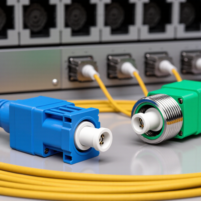
An SC fiber connector is a push-pull device used to join optical fibers. Its square body supports stable handling in patch panels and network equipment. The connector guides light through a precisely aligned ceramic ferrule. This small tube holds the fiber core at its center. Even slight misalignment can increase insertion loss.
The outer housing protects the ferrule during installation. A locking latch keeps the connector firmly seated. A rear boot supports the cable and reduces sharp bending near the fiber. Inside an adapter, a sleeve aligns two ferrules face to face. Light then passes across the polished end surfaces. In field inspections, dust is a frequent cause of poor performance. A clean connector may still fail if its end face is scratched. That detail is easy to overlook.
An SC fiber connector aligns and secures optical fibers through a simple push-pull design. Each fiber sits inside a precisely bored ceramic ferrule. The ferrule holds the fiber core near its center. A square key fits into the adapter’s matching slot. This prevents unwanted rotation during connection.
Inside the adapter, a split alignment sleeve guides two ferrules together. It keeps their polished end faces on the same axis. A small spring behind each ferrule creates steady pressure. That pressure reduces microscopic gaps and helps maintain stable optical transmission. The outer housing then locks into place with a push-pull latch. It feels firm, but it should never require force.
Cleanliness matters more than many installers expect. A tiny dust particle can block part of the core or increase insertion loss. Practical checks include inspecting the end face, cleaning it with approved tools, and testing the link afterward. Do not touch the polished surface. It is easy to assume a connector is secure because it clicks. That assumption is incomplete. A damaged key, worn sleeve, or loose adapter can still allow movement. I have found that gentle handling often protects performance better than repeated reconnection. Alignment is precise, yet not indestructible. Temperature changes and cable tension can also disturb the connection over time. Reserve enough slack near the panel, and keep the cable bend within its specified limit.
An SC fiber connector uses a square push-pull body and a ceramic ferrule to align optical fibers. Its keyed shape prevents incorrect orientation during connection. In practical installations, this simple design reduces handling errors, but only when the end face remains clean.
Start by removing the protective caps and checking the connector and adapter under proper inspection lighting. A tiny dust particle can cause insertion loss or permanent scratches. Clean both end faces with approved lint-free tools, then inspect them again. Do not touch the ferrule tip. Keep the caps nearby; leaving them on a workbench invites contamination.
Hold the connector by its body, not the fiber cable. Match the key with the adapter slot. Push the connector straight in until you feel or hear a light click. Never twist it during insertion. The locking mechanism should seat firmly without excessive force. A loose fit may indicate damage, poor alignment, or an unsuitable adapter. Remove it carefully by pressing the release tab and pulling the body straight back.
Use a visual fault locator or power meter to verify the link. The light path may work even with avoidable signal loss. That is easy to miss. If readings are unstable, inspect the end face again before replacing components. In hands-on work, rushing the cleaning step causes more trouble than the connection itself, and that habit deserves correction.
The chart shows the calculated optical power remaining after repeated SC connector mating cycles. It uses a typical single-mode insertion loss of 0.20 dB per connection and the optical transmission formula T = 10−loss/10. Actual performance varies with connector condition, alignment, cleanliness, and installation quality.
During connection, the SC housing guides the ceramic ferrules together, the keyed body maintains correct alignment, and the coupling mechanism holds the end faces in contact. Each additional mating can introduce a small amount of insertion loss.
An SC fiber connector uses a square, push-pull housing and a 2.5 mm ferrule. The ferrule centers the fiber core, while a spring keeps the end faces pressed together. Its locking action feels simple. That simplicity makes field installation quick, especially inside distribution panels and wall outlets. When inserted, the connector key aligns the optical path and prevents unwanted rotation.
Performance depends on more than connector shape. Insertion loss shows how much optical power disappears at the joint. Return loss indicates reflected power, which can disturb sensitive transmitters. A polished end face usually provides stable readings, but dust can change them quickly. SC connectors commonly come in simplex and duplex versions. Simplex carries one fiber; duplex carries two. Single-mode assemblies require precise alignment, while multimode assemblies often allow broader tolerances. Temperature range, pull strength, mating durability, and repeatability also deserve inspection.
The common polish types are UPC and APC. UPC has a slightly curved end face, while APC adds an approximately eight-degree angle to reduce back reflection. APC parts must match APC adapters; mixing polish types is a careless mistake. Color coding helps, but it is not enough. Check the label and inspect the end face. In practical troubleshooting, a connector may look clean yet produce excessive loss. Cleaning, retesting, and checking adapter wear can reveal the cause. Published limits vary by application, so measured results should guide acceptance. I still find connector selection less mechanical than it appears. The right type depends on link budget, available space, maintenance habits, and future upgrades.
| Data Dimension | Specification or Type | Typical Value / Description | Practical Significance |
|---|---|---|---|
| Connector Name | SC fiber connector | SC means Subscriber Connector or Square Connector. | A standardized fiber-optic connector with a square push-pull housing and a 2.5 mm ferrule. |
| Connection Mechanism | Push-pull coupling | The connector is inserted until it latches and pulled straight back to disconnect. | Provides simple, repeatable installation without threaded tightening. |
| Ferrule Diameter | Ceramic or compatible precision ferrule | 2.5 mm nominal diameter | Aligns the fiber cores accurately to reduce coupling loss. |
| Fiber Alignment | Butt-coupled fiber ends | The polished end faces of two fibers meet inside an alignment sleeve. | Maintains optical continuity while minimizing lateral and angular misalignment. |
| Typical Insertion Loss | Standard single-mode or multimode assembly | Approximately 0.2–0.5 dB, depending on quality, polish, cleanliness, and test conditions | Lower insertion loss preserves more of the available optical power budget. |
| Typical Return Loss | UPC-polished connector | Commonly about 50 dB or higher for a qualified single-mode assembly | Reduces reflected light in applications that use sensitive transmitters or receivers. |
| Typical Return Loss | APC-polished connector | Commonly about 60 dB or higher for a qualified single-mode assembly | The angled end face directs reflected light away from the optical source. |
| Polish Type | PC | Physical Contact polish with a slightly rounded fiber end face | Used where moderate back-reflection performance is acceptable. |
| Polish Type | UPC | Ultra Physical Contact polish with improved end-face geometry | Provides lower back reflection than basic PC polishing; the mating polish type must match. |
| Polish Type | APC | Angled Physical Contact polish, normally using an approximately 8-degree end-face angle | Offers very low back reflection for systems such as analog transmission, high-speed links, and passive optical networks. |
| Fiber Mode | Single-mode SC | Typically used with 9/125 µm fiber | Designed for long-distance, high-bandwidth, and low-dispersion transmission. |
| Fiber Mode | Multimode SC | Commonly used with 50/125 µm or 62.5/125 µm fiber | Suitable for many short- and medium-distance premises and data-center links. |
| Fiber Count | Simplex SC | One fiber in one connector position | Used for one optical channel or one transmit/receive path. |
| Fiber Count | Duplex SC | Two simplex connector positions joined by a duplex clip or housing | Supports two fibers, commonly for separate transmit and receive channels. |
| Boot Orientation | Standard boot | Strain-relief boot aligned with the cable axis | Protects the fiber-cable transition from excessive bending and pulling. |
| Boot Orientation | Right-angle boot | Boot directs the cable toward a side or downward position | Helps manage cable routing in dense patch panels and equipment spaces. |
| Cable Termination | Field-installable SC | Installed on-site using an appropriate termination method | Useful for custom cable lengths and service work, provided end-face quality is controlled. |
| Cable Termination | Factory-terminated SC | Preassembled and tested before shipment | Usually provides more consistent optical performance and faster installation. |
| Housing Function | Keyed square body | Square housing guides insertion and helps prevent incorrect rotational alignment. | Improves handling consistency and supports high-density patching. |
| Retention Method | Latch and locking features | The push-pull latch holds the connector in an adapter. | Reduces accidental disconnection caused by ordinary cable movement. |
| Environmental Protection | Standard indoor SC | Designed primarily for controlled indoor environments | Requires protection from dust, moisture, chemicals, and excessive mechanical stress. |
| Environmental Protection | Ruggedized or sealed SC variant | May include seals, protective boots, or reinforced housings | Used when higher resistance to moisture, vibration, dust, or outdoor exposure is required. |
| Interoperability | Adapter and connector compatibility | Both sides should use the same connector geometry, fiber mode, and polish type. | Mixing incompatible polish types, such as UPC and APC, can damage end faces and cause excessive loss. |
| Cleaning Requirement | End-face cleanliness | Inspect and clean the ferrule end face before mating. | Dust and residue can increase insertion loss, reduce return loss, and permanently damage polished surfaces. |
| Common Applications | Telecommunications and premises networks | Patch panels, optical distribution frames, fiber termination boxes, access networks, and equipment links | The robust latch and relatively large housing make SC connectors practical for general fiber infrastructure. |
| Reference Standard | SC connector interface | Covered by international fiber-optic connector interface specifications, including IEC 61754-4 | Standardized geometry supports compatibility between compliant connectors and adapters. |
An SC fiber connector uses a square, push-pull housing and a 2.5-millimeter ferrule. The ferrule aligns the fiber cores inside an adapter. When an installer pushes the connector into place, an internal spring maintains contact between the polished end faces. Pulling the housing releases it without twisting the cable. This simple action makes SC connections practical for technicians working in crowded cabinets or ceiling spaces.
SC connectors commonly appear in telecom distribution frames, fiber-to-the-home terminals, data networks, and test equipment. Their large body is easy to grip, even with work gloves. The push-pull design also reduces accidental rotation during maintenance. Single-mode versions support long-distance links, while multimode versions suit shorter building networks. In field installations, technicians still need to inspect and clean every end face. A tiny dust particle can increase loss or create unstable readings.
The main limitation is size. An SC connector occupies more panel space than smaller designs, which matters in high-density racks. Its locking mechanism is reliable, but repeated rough handling can damage the housing or adapter. Performance also depends on polishing quality, alignment, cable routing, and bend radius. One overlooked detail can weaken the link. SC connectors are not automatically the best choice for every upgrade, especially where space is severely limited. Testing insertion loss and return loss remains necessary after installation. A connector may feel secure but still perform poorly.
It is a push-pull connector for joining optical fibers. Its square housing supports steady handling in panels and equipment. A ceramic ferrule centers the fiber core. Small errors can raise insertion loss.
A keyed square body matches the adapter slot. This prevents unwanted rotation. Inside the adapter, a split sleeve guides both ferrules onto one axis. Small springs maintain pressure between the polished ends.
The main parts include the housing, ceramic ferrule, latch, rear boot, and internal spring. The housing protects the ferrule. The boot supports the cable and limits sharp bending. The latch keeps the connector seated.
Inspect the connector and adapter under suitable lighting. Clean both end faces with approved lint-free tools. Match the key with the adapter slot. Push straight until a light click occurs. Do not twist the connector.
Dust can block part of the fiber core and increase signal loss. Scratches may cause permanent performance problems. Never touch the polished surface with your fingers. Clean, inspect, and clean again if needed.
Check that the latch clicks into place without excessive force. The connector should feel firm, not strained. A click alone proves little. A damaged key, worn sleeve, or loose adapter can still allow movement.
Inspect both end faces again before replacing components. Check the adapter, latch, and cable position. Use a visual fault locator or power meter for verification. Rushing the cleaning step often creates the problem.
Keep enough slack near the panel. Stay within the cable’s specified bend limit. Avoid pulling, twisting, or sharply bending the rear boot. Temperature changes and cable tension may disturb alignment over time. Gentle handling works better.
An Sc Fiber Connector is a push-pull optical fiber connector designed to create a precise, stable connection between fiber cables and network equipment. Its main components include a protective housing, ferrule, alignment sleeve, latch mechanism, and strain-relief boot. The ferrule holds the fiber end, while the alignment sleeve centers it accurately with another fiber or adapter. During connection, the fiber is cleaned and inserted into the connector, the latch is guided into the adapter, and a gentle push secures the assembly. The aligned fiber cores then allow light signals to pass with minimal loss and reflection.
SC connectors are valued for their simple operation, reliable locking structure, durable performance, and relatively low installation complexity. Common variations may include simplex, duplex, single-mode, and multimode designs. They are widely used in telecommunications, data networks, fiber distribution systems, security equipment, and testing environments. However, their larger size may limit use in high-density panels, and performance can decline if the end face becomes contaminated or damaged.

Stpete Electronics