What Are the Top Types of Horizontal Connectors?

Time:2026-11-22 Author:Ethan
0%

Horizontal connectors appear in systems where board space, signal direction, and access matter. They join components across a horizontal path, often inside compact equipment. The right type can make assembly cleaner. The wrong one can complicate routing, servicing, or signal performance. Small details matter.

A practical comparison should cover board-to-board, wire-to-board, and card-edge designs, along with their common variations. Look closely at pitch, contact count, mounting style, mating height, current rating, and environmental demands. A connector’s shape alone tells only part of the story. For example, a low-profile board-to-board pair may save vertical space, while a wire-to-board option can simplify a service connection. But trade-offs remain. A tighter pitch may demand more careful alignment. That is easy to underestimate.

An expert quotation belongs here, but no source article or verifiable quotation was provided: [Insert a verified Horizontal Connector expert’s name and exact quotation.] It should not be invented. With a confirmed source, the quote can frame the guide’s central point: connector selection depends on the real operating conditions, not just a product label. This overview will compare the leading horizontal connector types, explain where each fits, and flag details worth checking before choosing a part. Some applications resist neat categories. That deserves a closer look.
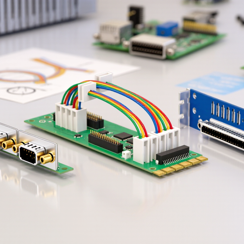
What Are the Top Types of Horizontal Connectors?

What Defines a Horizontal Connector and How Is It Oriented?

A horizontal connector is defined by its mating direction, not simply by how its housing looks. On a printed circuit board, its mating axis runs parallel to the board surface. A vertical connector’s mating axis points away from that surface. This distinction matters when a cable must exit sideways through a narrow enclosure. In a right-angle board connector, the contacts turn the electrical path while the plug approaches from the board’s edge. Check the product drawing: “horizontal” can describe mounting orientation differently across manufacturers.

Common horizontal formats include board-to-board, wire-to-board, and edge-card connectors. Their uses differ, but clearance remains a practical concern. A plug may fit on paper, then collide with a case wall or nearby cable. Measure the full mated assembly, including latch access and cable bend space. Allow room for service, too. A 2023 Grand View Research connector-market report estimated the global market at USD 84.1 billion in 2022 and projected 6.3% annual growth through 2030. That figure covers connectors broadly, not horizontal types alone. Still, it reflects how widely connectors serve electronics, where orientation can shape packaging choices. Drawings are not always clear enough; verify the mating axis before finalizing a layout.

What Are the Top Types of Horizontal Connectors?

Representative nominal pitches for common side-entry and right-angle connector types

Horizontal connectors are oriented so the mating connection or cable runs parallel to the circuit board. Common examples include right-angle wire-to-board and board-to-board connectors, side-entry FFC/FPC connectors, and right-angle card-edge connectors. The pitch values shown are representative examples, not fixed values for every design.

Right-Angle PCB Headers for Compact Board Connections

Among horizontal connector options, right-angle PCB headers are useful when a board needs a low-profile connection along its edge. Their solder tails enter the PCB, while the mating interface points sideways, keeping a cable or daughterboard close to the board plane. This can reduce height inside a shallow enclosure and leave more room above the board. It may also improve access when components crowd the top surface. Small detail. The connector still needs room for its mating part and cable bend.

Selection should start with the mechanical envelope, not pin count alone. Check pitch, circuit count, termination style, and mating orientation against the board drawing. Confirm current and voltage ratings in the component documentation, then allow space for solder fillets and assembly tools. For a cable connection, inspect the bend radius and strain relief; a header may fit on paper but press against a nearby wall. That happens. Right-angle headers can also make inspection or rework awkward when placed beside tall components. A few millimeters of clearance can decide whether assembly is straightforward. The angle helps, but it does not replace a complete fit check.

Horizontal Wire-to-Board Connectors for Cable Routing

Horizontal wire-to-board connectors help route cables parallel to a circuit board, which can save height inside compact equipment. A right-angle header turns the cable toward the board’s edge. Side-entry versions guide wires into the housing from the side, while low-profile designs reduce the space needed above the board. Some types include friction locks or latches to resist vibration-related loosening.

Choose a connector by checking its current rating, pitch, wire size, and required mating direction. Then measure the cable bend and nearby parts, not just the connector body. In a tight enclosure, a cable can press against a lid even when the connector itself fits. A latch may improve retention, but it can also make access harder during service. I have found that routing drawings sometimes miss this practical detail.

Tips: Leave room for the cable’s natural bend. Check the mating cycle and retention method against the actual use. Test a sample assembly before finalizing the board layout; measurements alone can be misleading.

Side-Entry FFC and FPC Connectors for Flat Cables

What Are the Top Types of Horizontal Connectors?

Side-Entry FFC and FPC Connectors for Flat Cables

Side-entry FFC and FPC connectors accept flat cables parallel to the circuit board. This horizontal layout can save height in compact devices, such as handheld instruments or slim control panels. A hinged or sliding actuator often secures the cable, while some designs use friction alone. Small parts matter. Before choosing a connector, check the cable pitch, contact count, thickness, and contact-side orientation against the product specifications. FFC cables are typically flat conductors held between insulating films; FPCs are flexible printed circuits. They may fit similar connector families, but compatibility should never be assumed.

Tips: Open the actuator gently, insert the cable straight to its stop, then close the lock evenly. A skewed cable can cause intermittent contact. Confirm the required insertion depth in the connector drawing.

Side-entry connectors are useful when cables must turn across a board rather than rise above it. However, low-profile designs can be harder to inspect or rework, especially in crowded assemblies. Retention strength, operating cycles, and available access vary by model. A connector that fits neatly on a drawing may be awkward to service in a real enclosure; that detail is easy to overlook. Check the assembled cable path and clearance before finalizing the layout.

Board-to-Board and Edge Connectors for Parallel Assemblies

In parallel assemblies, horizontal connectors link circuit boards while keeping their faces aligned and spacing predictable. Board-to-board connectors use mating halves to bridge the gap. Their stack height sets clearance for components and airflow. Small details matter. Contact pitch, pin count, and board spacing affect routing and assembly access.

Edge connectors place plated contacts along a board’s edge. With a right-angle socket, the board can meet a neighboring board in a compact, parallel layout. This can reduce connector height, but the exposed fingers need careful alignment. A slight insertion angle may cause uneven contact or wear. Not always obvious.

Choose between these types by checking signal speed, current, mating cycles, and available support points. For high-speed links, review the connector’s impedance and keep nearby traces short and consistent. For power, confirm contact ratings and allow for heat. Vibration can loosen an unsupported assembly, so use standoffs or other mechanical support where needed. A CAD model may show a clean fit, yet real boards can flex during insertion. That deserves a prototype check, even when the design looks simple.

What Are the Top Types of Horizontal Connectors? — Board-to-Board and Edge Connectors for Parallel Assemblies

Connector Type How It Connects Parallel Boards Typical Features Advantages Key Selection Considerations Common Applications
Mezzanine Board-to-Board Two surface-mounted connector halves mate face-to-face, keeping the printed circuit boards parallel with a defined gap between them. Available in low-profile and higher-stacking-height versions; contact counts, pitches, and mating heights vary by series. Compact, direct board-to-board connection; can support dense signal routing in stacked assemblies. Check the required board spacing, contact count, current and signal requirements, alignment tolerance, and allowable mating cycles. Compact electronics, embedded modules, control boards, and stacked circuit assemblies.
Board-to-Board Header and Socket A pin header on one board mates with a socket on the other; straight versions can hold boards parallel when mounted in the appropriate orientation. Commonly offered in through-hole or surface-mount forms, with single- or dual-row layouts and multiple pin counts. Simple, widely used format with options for board spacing and straightforward assembly. Confirm the mating orientation, pin alignment, board support, electrical ratings, and whether the assembly needs a removable connection. Control electronics, instrumentation, development boards, and modular equipment.
Floating Board-to-Board A board-to-board mating system incorporates limited movement in the connector interface to accommodate small positional offsets between parallel boards. Designed with a specified allowance for misalignment; movement and tolerance limits depend on the connector design. Can help reduce assembly stress when board positions vary slightly during installation. Verify the permitted X, Y, and angular misalignment, stacking height, retention, and the manufacturer’s mating guidance. Multi-board equipment, industrial controls, and assemblies with tighter mechanical tolerance challenges.
Card-Edge Connector Exposed conductive pads along the edge of one circuit board insert into a card-edge socket. A socket mounted to a second board can form a parallel-board connection, depending on its orientation. Uses plated edge contacts instead of a separate connector half on the inserted board; contact layout and edge geometry must match the socket. Can reduce parts on the inserted board and provides a removable plug-in interface. Match the pad pattern, board thickness, contact plating, insertion depth, and socket orientation; protect the exposed contacts from damage. Expansion cards, removable modules, and plug-in circuit assemblies.
Backplane and Daughtercard Connector A daughtercard mates with a connector mounted on a backplane; the mechanical layout determines whether the boards are parallel or arranged at another angle. Designed for multi-board systems and may combine signal, power, or ground contacts in one interface. Supports modular system architectures and can provide a shared interconnection point for several boards. Assess signal integrity, current capacity, insertion force, board alignment, and system-level mechanical support. Telecommunications, computing, test systems, and other modular electronic equipment.

Actual pitch, board spacing, current capacity, data rate, and misalignment tolerance depend on the specific connector design. Confirm the mechanical drawing and electrical specifications before selecting a part.

FAQS

What is a right-angle PCB header used for?

It connects a cable or daughterboard sideways to a circuit board. This can reduce height in a shallow enclosure.

How does a horizontal connector help with cable routing?

It guides the cable parallel to the board. The cable still needs room to bend naturally.

What should I check before choosing a right-angle header?

Check pitch, circuit count, termination style, and mating direction against the board drawing. Pin count alone is not enough.

How can I tell whether the connector will fit inside an enclosure?

Measure the connector, mating part, cable bend, and nearby walls. A lid can press against a cable even when the connector fits.

Why do current and voltage ratings matter?

Confirm both ratings in the component documentation. Also match the connector to the wire size and expected use.

Do latches or friction locks always make a connector better?

They can help resist loosening from vibration. But they may make service access harder.

What assembly clearances should I allow?

Leave space for solder fillets and assembly tools. A few millimeters may make inspection or rework easier.

Should I test a sample before finalizing the board layout?

Yes. Try the assembly with the actual cable and nearby parts; measurements can miss small fit problems. I may be overthinking it, but check the bend twice.

Conclusion

A Horizontal Connector is designed to make electrical connections parallel to a circuit board or along a device’s surface, helping manage space and cable direction in compact assemblies. Its orientation can reduce the height of a connection and guide wires or flat cables toward the side of a board, making it useful in layouts where vertical clearance is limited.

Common types include right-angle PCB headers for connecting boards with a low profile, horizontal wire-to-board connectors for routing individual wires, and side-entry FFC or FPC connectors for thin, flexible cables. Board-to-board and edge connectors can also link parallel assemblies or connect at a board’s edge. Choosing among these options depends on the available space, cable type, connection layout, and the need for a secure, practical fit.


Ethan

Ethan

Ethan is a seasoned marketing professional with a deep expertise in our company's innovative product line. With a passion for sharing knowledge and insights, he takes the lead in regularly updating our corporate blog, where he explores industry trends, product features, and effective marketing......