Pin Connector Types are not interchangeable details. They determine how power, signals, and mechanical forces move through a device. A compact board connector may use fine-pitch contacts, while an automotive connector needs sealing, vibration resistance, and reliable locking.
The market reflects this complexity. Bishop & Associates reported that the global electronic connector industry reached approximately USD 84 billion in 2023. Grand View Research also projects steady market growth through 2030, driven by electric vehicles, industrial automation, telecommunications, and data centers. These figures show strong demand, but market size alone does not identify the correct connector.
Performance depends on contact material, plating, pitch, current rating, mating cycles, and environmental exposure. A gold-plated contact may suit low-level signals, while a thicker power pin may handle higher current. Small differences matter.
“Electrical contacts are the critical interface between an electrical circuit and the outside world,” explains Dr. Paul G. Slade, an authority on electrical contact engineering and author of The Electrical Contacts Handbook. His observation clarifies why connector selection requires more than matching a shape.
A connector can look suitable and still fail under heat, moisture, or repeated movement. That is the uncomfortable part. Product designers sometimes prioritize cost before testing real operating conditions.
This guide examines Pin Connector Types by structure, application, electrical capacity, and installation method. It also considers practical trade-offs. No single pin design fits every system. Reliable selection begins with the actual environment, not the catalog photograph.
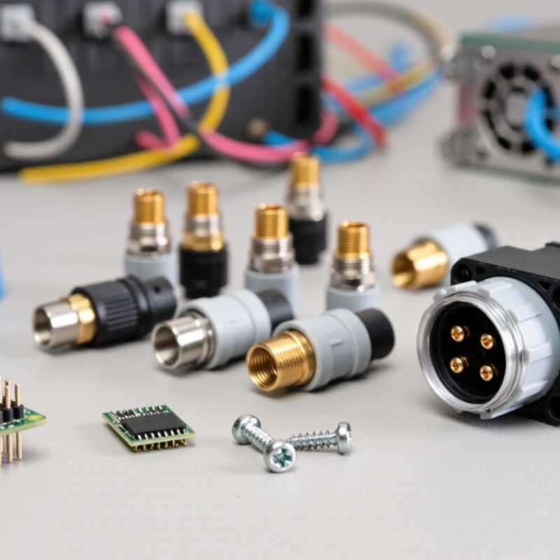
A pin connector joins electrical circuits through small conductive pins and matching sockets. Each pin carries power, signals, or a ground path. The housing keeps contacts aligned and prevents accidental contact. During mating, spring terminals press against the pin surface. This pressure creates a stable electrical path, even when equipment experiences vibration.
Connector types differ because applications demand different contact shapes, spacing, and protection. A 2.54-millimeter pitch may suit a circuit board, while a smaller pitch saves space in dense electronics. Locking versions resist cable movement. Sealed versions reduce moisture and dust exposure. A 2024 industry market report estimated the global connector market above 80 billion U.S. dollars, reflecting demand across vehicles, factory equipment, and communication systems. The number is broad, though. Market definitions vary between reports.
Electrical performance depends on more than pin count. Contact resistance, insertion force, current rating, and plating quality all matter. IEC 60512 testing methods evaluate connection resistance, mechanical endurance, and environmental performance. On a workbench, a loose pin can cause intermittent faults that appear only during vibration or heating. That makes visual inspection insufficient. Designers should verify the connector’s rated voltage, current, temperature, and mating cycles. A practical mistake is choosing a connector by appearance alone. It may fit physically but fail electrically. Small details matter.
| Connector Type | How It Works | Typical Contact Arrangement | Typical Applications | Main Advantages | Key Limitations |
|---|---|---|---|---|---|
| Male Pin Header | Straight or angled metal pins enter matching sockets or receptacles. The pins are commonly soldered directly to a printed circuit board. | Single-row or dual-row layouts; common pitches include 2.54 mm and 2.00 mm. | Board-to-board connections, programming interfaces, test points, and wire-to-board assemblies. | Low cost, simple construction, easy inspection, and many pin-count options. | Exposed pins can bend, short, or collect contamination; usually not intended for frequent unmated cycles. |
| Female Socket Header | Spring contacts inside the socket grip the mating male pins and create an electrical path while providing mechanical retention. | Single-row, dual-row, or multi-row configurations; often matched to standard pin-header pitches. | Removable circuit boards, development systems, modular electronics, and replaceable wiring harnesses. | Protects contacts from accidental touching and supports convenient disconnection. | The socket adds height and cost; repeated mating can reduce spring-contact force over time. |
| Shrouded Pin Header | A plastic shroud surrounds the pins and guides a keyed mating connector into the correct position. | Usually dual-row, with polarization features and an indexed mating orientation. | Ribbon-cable assemblies, board-to-board connections, and applications requiring error-resistant insertion. | Reduces reversed insertion, improves alignment, and protects the pins mechanically. | Larger and less flexible than an exposed header; the shroud can limit available board space. |
| Board-to-Board Pin Connector | Mating pins and sockets connect two parallel or perpendicular circuit boards, transferring power and signals between them. | Single or multiple rows; pitch and stack height are selected according to board spacing and routing needs. | Control modules, embedded computers, instrumentation, and compact electronic assemblies. | Saves cable space, supports modular designs, and can provide high contact density. | Requires accurate board alignment; vibration and tolerances may affect contact reliability. |
| Circular Pin Connector | Pins and sockets are arranged inside a round housing. Coupling may use threaded, bayonet, snap, or push-pull mechanisms. | Low to high pin counts, commonly arranged in concentric or circular patterns. | Industrial equipment, sensors, automation systems, audio equipment, and power or signal cables. | Strong mechanical retention, good strain relief, and optional sealing against dust or moisture. | Often bulkier than rectangular connectors and may require more panel space. |
| D-Shaped Pin Connector | Male pins and female contacts sit in a D-shaped shell that provides polarization and helps prevent incorrect orientation. | Multiple rows with standardized contact layouts; screw locks are common for cable retention. | Computer interfaces, industrial controls, instrumentation, and serial communication equipment. | Clear orientation, reliable shell support, and secure cable mounting. | Lower contact density than some modern compact connectors; shell size can be relatively large. |
| Pogo Pin Connector | A spring-loaded pin compresses against a conductive pad or mating contact, maintaining pressure despite small movement or tolerance differences. | Individual pins or dense arrays; contact travel is selected according to the required compression range. | Charging docks, test fixtures, removable modules, wearable devices, and temporary electrical contacts. | Handles misalignment, supports frequent mating, and eliminates the need for a conventional socket in some designs. | More complex and costly; spring force, contamination, and contact wear must be managed. |
| High-Current Pin Connector | Larger pins or multiple parallel contacts carry higher current while the housing maintains spacing and prevents accidental contact. | Fewer, larger contacts with greater separation than signal connectors; exact current capacity depends on design and cooling. | Battery systems, power distribution, motors, industrial equipment, and power supplies. | Designed for lower contact resistance, increased thermal capacity, and secure power transfer. | Larger physical size, higher insertion force, and greater safety requirements than low-power signal connectors. |
| Right-Angle Pin Connector | The pins exit the connector body at approximately 90 degrees, allowing a cable or mating board to run parallel to the circuit board. | Single-row, dual-row, or multi-row layouts; available in various pitches and pin counts. | Compact enclosures, edge connections, cable routing around circuit boards, and low-profile assemblies. | Improves cable direction, saves vertical space, and can simplify enclosure design. | Less flexible for straight cable routing; the bend area requires sufficient clearance and strain relief. |
Electrical systems have different current, space, signal, and environmental requirements. One design cannot fit every application.
Current and voltage influence pin size, spacing, insulation, and contact strength. Small signals need fine contacts. Motors need stronger ones.
Spacing affects insulation, clearance, and signal quality. Wider spacing can reduce electrical risk in higher-voltage circuits.
Heat, dust, moisture, and vibration can damage unsuitable connectors. Check sealing, temperature limits, materials, and locking features.
No. More pins increase wiring density but may complicate testing, repair, and installation. More is not automatically better.
Straight pins suit vertical board connections. Right-angle pins route cables along an enclosure wall.
Locks help prevent separation during vibration or cable movement. A small latch can prevent hours of troubleshooting.
High-frequency systems need controlled impedance, short signal paths, and careful grounding. Layout matters greatly.
Not always. Keying, contact ratings, wire size, and mating design may differ. I once assumed interchangeability and missed those details.
Verify current, voltage, mating cycles, temperature, cable bend radius, service space, and installation conditions. Datasheets help, but inspection can reveal hidden problems.
Pin Connector Types are designed to meet the varied needs of electrical and electronic systems. A pin connector creates a detachable connection by using metal pins and matching sockets or contact points to transfer electrical current and signals. Different types exist because applications require different levels of power, signal reliability, connection density, protection, and installation flexibility. Their designs may vary in pin arrangement, shape, size, spacing, contact structure, locking method, and housing style.
When selecting the right pin connector, engineers consider voltage and current ratings, signal frequency, available space, environmental conditions, connection cycles, assembly method, and required mechanical strength. Some connectors are intended for compact circuit boards, while others support cable-to-cable or panel-mounted connections. By matching connector design and function to the application, Pin Connector Types can provide stable performance, easier maintenance, and dependable communication or power delivery across industrial equipment, consumer electronics, vehicles, and other modern systems.

 Stpete Electronics