Engineered to work seamlessly with board-level shielding systems to ensure signal integrity across high-speed telecommunication networks.
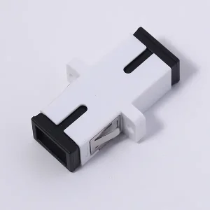
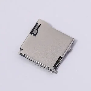
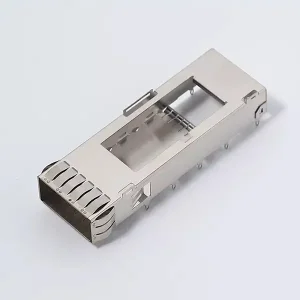
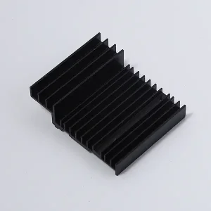
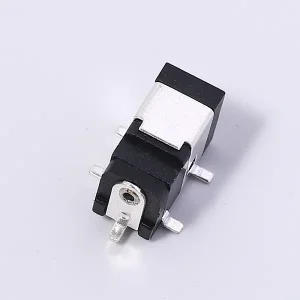
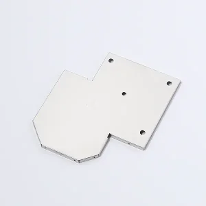
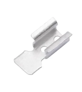
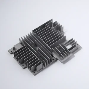
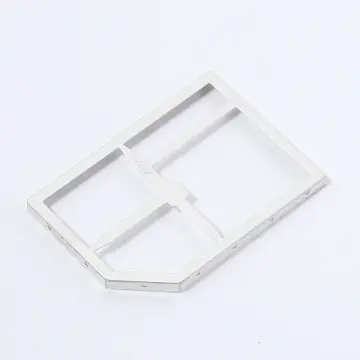
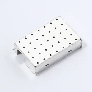
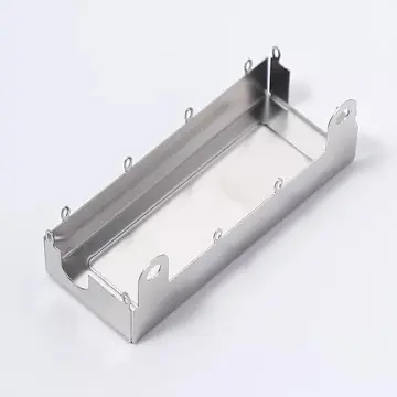
In modern high-speed circuit designs, electromagnetic interference (EMI) and radio-frequency interference (RFI) represent critical hurdles. As clock speeds surge, system architectures shrink, and wireless technologies saturate the airwaves, maintaining clean signals on a PCB is paramount. A through-hole shielding frame (also called a board-level shielding can, frame, or EMI cage) serves as a physical barrier. It isolates sensitive sub-assemblies—such as RF transceivers, microcontrollers, switch-mode power circuits, and analog front-ends—from background noise and cross-coupling.
While surface-mount technology (SMT) shielding has gained widespread adoption due to process speed, through-hole shielding frames remain indispensable in industrial, military, aerospace, and automotive environments. The mechanical anchorage offered by pins penetrating the PCB substrate provides outstanding resistance to high vibration, thermal expansion stresses, and mechanical shocks. This technical whitepaper delves into the engineering principles, certification pathways, global supply dynamics, and manufacturing excellence behind CE-certified board-level shielding frames.
A shielding frame behaves as a Faraday cage. According to electromagnetic wave propagation physics, the effectiveness of an EMI shield depends on electrical conductivity, magnetic permeability, and the integrity of the ground connection. The ground path must present extremely low impedance. Through-hole pins solder directly into grounding vias that connect to multiple internal ground planes. This drastically reduces parasitic inductance compared to surface-mount pads, providing superior attenuation of high-frequency harmonics (above 5 GHz).
| Parameter | Through-hole Shielding Frames (THT) | Surface-mount Shielding Cans (SMT) |
|---|---|---|
| Mechanical Anchorage | High (Pins secured through board vias) | Medium (Solder pad adhesion only) |
| Vibration Resistance | Excellent (MIL-STD-202 standard compliant) | Moderate (Risk of joint fatigue) |
| RF Ground Impedance | Low (Direct multi-layer plane access) | Moderate (Surface path limitation) |
| Thermal Performance | Excellent heat dissipation path through pins | Limited thermal conduction via periphery |
| Field Maintenance | Requires desoldering pins or removable cover | Removable covers standard |
To market electronic hardware in the European Economic Area (EEA), compliance with the CE Marking directives is legally mandatory. While passive shielding frames themselves are not standalone electrical devices and thus do not carry independent CE marks under the Low Voltage Directive, they are critical to the system-level compliance of the final equipment under the EMC Directive (2014/30/EU) and the Radio Equipment Directive (RED - 2014/53/EU).
Working with a certified through-hole shielding frame manufacturer ensures that the materials, tolerances, and design geometries conform to standards that facilitate system-level CE testing. Key validation parameters include:
The manufacturing of through-hole shielding frames is a disciplined exercise in progressive die stamping. To avoid RFI leaks, shielding cans require precise dimensional stability. Any deviation in wall straightness or peg pitch can cause mechanical interference, slowing automated PCB assembly lines.
The choice of alloy dictates electrical resistivity, permeability, mechanical rigidity, and corrosion characteristics:
Precision stamping presses (ranging from 45-ton to 110-ton capacity) utilize multi-station progressive dies to form the frame, punch out pattern apertures (such as cooling vents and internal dividers), bend the locking detents, and cleanly shear the through-hole mounting pins. Progressive die tolerances are held within ±0.02 mm to guarantee total conformity to target footprint geometries.
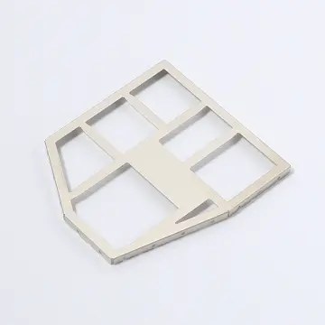
Modern telecommunication devices (e.g., optical routers, switchgear, and RF transceivers) often require isolation of multiple stages within a single assembly. Integrated labyrinth frames feature internal metal dividers, allowing a single through-hole frame to create distinct shielding cells for the power amplifier, local oscillator, and digital processing chips. This reduces component count and PCB footprint.
A premier Chinese manufacturing enterprise providing state-of-the-art interconnect systems and precision board-level components since 2005.

Established in 2005, Wenzhou Stpete Electronics Technology Co., Ltd. has evolved into a leading high-tech enterprise specialized in the R&D, production, and international distribution of precision electronic connectors, switches, and high-frequency components. Operating out of our modern facility, we serve as a reliable partner to top-tier electronics manufacturing services (EMS) providers and original equipment manufacturers (OEMs) worldwide.
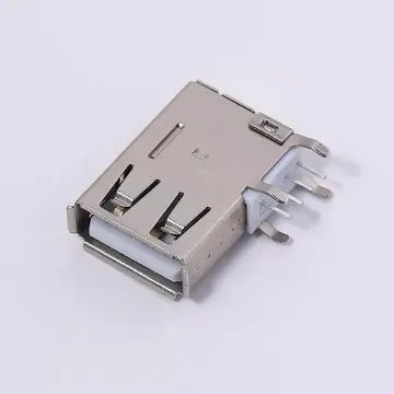
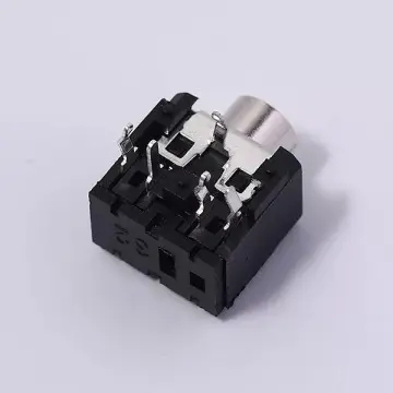
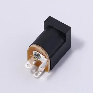
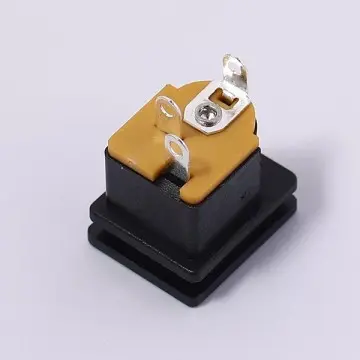
With over 20 years of technical experience, we maintain a comprehensive tooling shop equipped with state-of-the-art progressive stamping presses, high-speed CNC machining centers, and automated injection molding lines. Our capabilities enable us to produce premium RF terminals, PCB networks, DC power outlets, USB connectors, and bespoke board-level shielding frames that comply with international quality protocols.
Certified to ISO 9001, ISO 14001, and ISO 45001. Our inspection systems monitor every production stage to guarantee compliance and zero defects.
Over 30 R&D personnel driving innovation with an annual investment exceeding 15 million RMB, securing over 21 utility and structural patents.
Cooperating with leading global hardware and telecom brands, including Huawei and Hisense, to deliver high-volume, reliable components.
At Stpete Electronics, quality is guided by engineering discipline. Our inspection labs feature optical coordinate measuring machines (CMM) to verify the dimension of shielding frames, micro-hardness testers to check nickel-silver temper, and salt spray chambers to validate the anti-oxidation coatings of tin-plated assemblies.
Through our robust ERP tracking systems, we offer material traceability. From the incoming coil of alloy, through progressive stamping, to final automated packaging, each step is logged, satisfying the strict requirements of automotive and industrial customers.


Our core strength lies in our engineering team. We prioritize continuous training, and cultivate a corporate culture of collaboration. Team-building exercises foster deep relationships and communication across our production, design, and customer support divisions.
This team cohesion ensures that customer requirements are handled efficiently, with rapid response times and expert design support, bringing products from concept to market quickly.
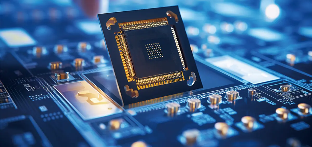
30+ technical R&D personnel, annual R&D investment of 15 million yuan+, 21 patents+.

Meticulous from raw material selection to final inspection to guarantee product safety.

Insert molding, finished product assembly, and automated production technology.
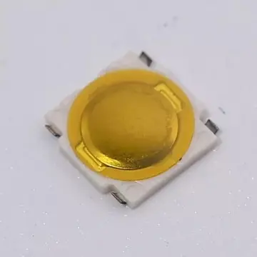
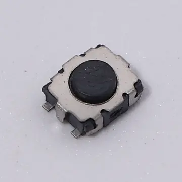
Explore our high-performance electronic components, including tactile switches and custom board connectors.
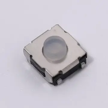
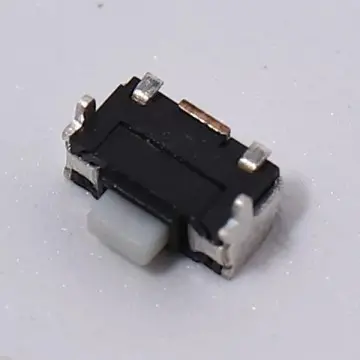
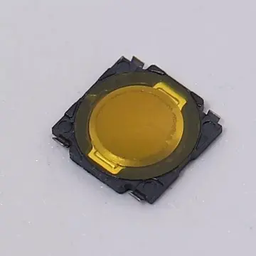
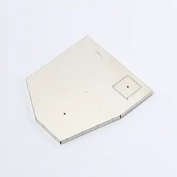
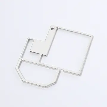
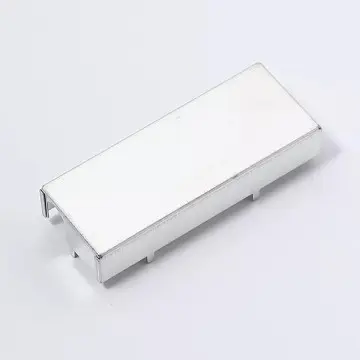

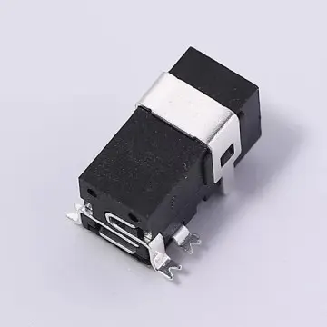
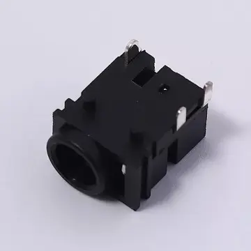
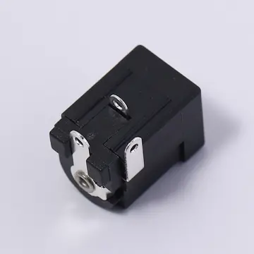
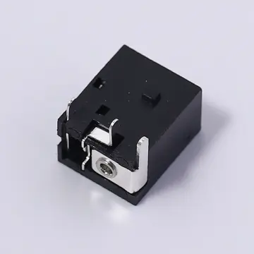
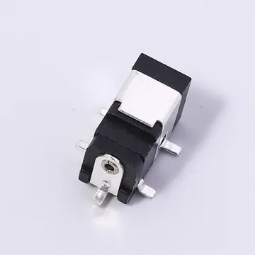
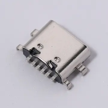
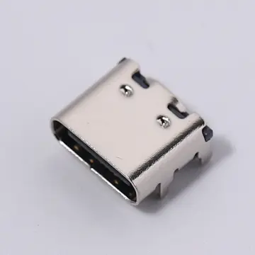
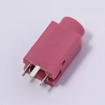
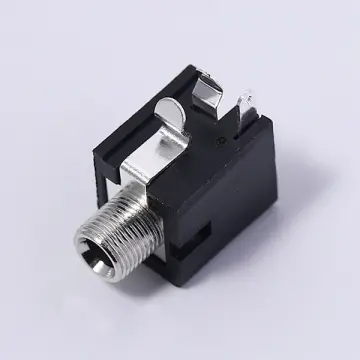
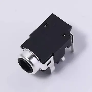
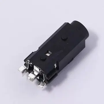

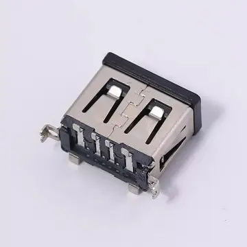
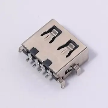
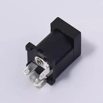
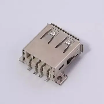
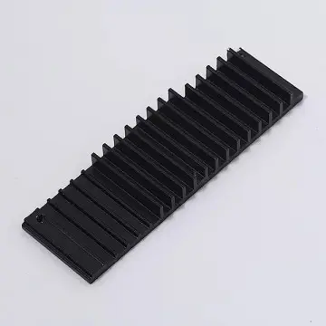
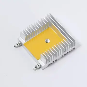
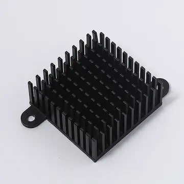
CE-certified through-hole shielding frames are deployed across multiple critical sectors where EMI suppression and physical endurance cannot be compromised:
Modern Electric Vehicles (EVs) utilize high-voltage traction inverters that generate massive electromagnetic noise. Through-hole shielding frames are deployed to enclose driver cards and control processors, preventing switching noise from corrupting delicate sensor signals in Advanced Driver Assistance Systems (ADAS) like radar and LiDAR modules.
In fiber-optic switches and routers, multi-gigabit transceivers (such as SFP, SFP+, and QSFP ports) operate at extremely high frequencies. Shielding frames isolate the electro-optical engines from neighboring ports, preventing inter-channel crosstalk and maintaining data transmission integrity.
In switch-mode power supplies (SMPS) and industrial motor control drives, magnetic radiation from inductors and transformers can cause severe system instability. High-permeability through-hole steel frames block these magnetic fields, maintaining compliance with European harmonized standards.
Addressing the primary technical and certification questions encountered by design engineers.
OEM/ODM quality solutions for power, telecommunications, and industrial interfaces.
 Stpete Electronics